...
🇮🇹 Meet SonnePower at REAS 2026 in Italy   |   Oct. 8–10, 2026   |   Centro Fiera Montichiari   |   Pavilion 2 – Stand C9 🇮🇹 Meet SonnePower at REAS 2026 in Italy   |   Oct. 8–10, 2026   |   Centro Fiera Montichiari   |   Pavilion 2 – Stand C9

Programmable CAN Bus Display Replacement Guide (2025)

Table of Contents

Programmable CAN bus displays are essential for mobile machinery and industrial systems, presenting critical data such as engine RPM, coolant temperature, and diagnostic trouble codes (DTCs). When a display fails or becomes obsolete, a proper replacement not only restores functionality but also upgrades usability and reliability.

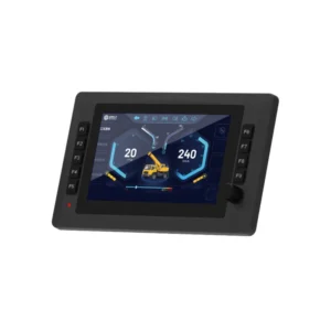
SonnePower  provides rugged, IP67-rated programmable CAN bus displays (4.3″, 7″, 10.1″, 12.1″) that support SAE J1939, CANopen, and custom CAN protocols—ideal for direct replacement or system upgrades.

This guide walks you through the complete process of replacing a programmable CAN bus display—from system assessment and product selection to installation, configuration, and testing—helping you minimize downtime and keep your equipment running reliably.

Step 1: Assess Your Current System

Before purchasing a replacement display, gather detailed information about your current system:

  • Identify the Communication Protocol: Verify whether the display uses SAE J1939, CANopen, or a proprietary CAN protocol.

  • Collect CAN Data: Obtain DBC files, message definitions, or parameter documentation from the equipment manufacturer.

  • Document Wiring and Power Requirements: Record the voltage range (12 V / 24 V), connector type, pinout, and grounding points.

  • Review Display Features: Note the screen size, resolution, number of pages, touch capability, button layout, and backlight brightness.

💡 Tip: Take clear photos of the wiring harness and connectors before removing the old display to make reinstallation easier.

Step 2: Choose the Right Replacement Display

A successful replacement begins with selecting a display that is fully compatible and built for durability. Consider the following factors:

  • Hardware Interface: Ensure CAN-H / CAN-L pinout, voltage range, and IP rating match your system.

  • Protocol Support: Verify that the display supports J1939, CANopen, NMEA2000, or your custom CAN protocol.

  • Programmability: Confirm support for GUI editors (e.g., CODESYS 3.5), data mapping, and alarm configuration.

  • Environmental Specifications: Evaluate operating temperature (-40 °C to +85 °C), vibration/shock resistance, and sunlight readability.

  • Future Expandability: Choose a model with dual CAN channels, Ethernet/USB ports, or digital I/O for future upgrades.

💡 SonnePower Solution: Our SD Series Rugged CAN Bus Displays offer dual CAN, IP67 protection, wide temperature range, and full CODESYS programmability—perfect for new installations or drop-in replacements.

Step 3: Safely Remove the Old Display

  • Power Down the System: Disconnect the machine’s main power supply to prevent electric shock or accidental short circuits.

  • Label Connectors: Clearly label each connector with masking tape or tags before unplugging to ensure correct reassembly.

  • Unbolt the Display: Carefully remove the screws or clamps securing the display, and store them in a safe container for reuse.

  • Inspect the Wiring Harness: Check for damaged wires or corroded connectors, and replace them before installing the new display.

Step 4: Install and Configure the New Display

  • Mounting: Position the new display into the panel cut-out or secure it on a compatible bracket. Install vibration isolators if recommended by the manufacturer.

  • Connect Wiring: Reconnect CAN_H, CAN_L, power, and ground leads per the wiring diagram. Double-check polarity and verify that termination resistors are properly installed.

  • Sealing: For outdoor applications, confirm that gaskets and seals are properly seated to maintain IP65/IP67 protection.

  • Power-On Check: Power on the system to confirm the display initializes correctly and performs a basic functionality check before reassembling the dashboard.

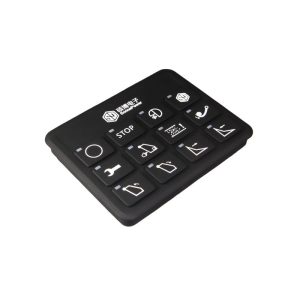
4.3 inch can bus display

Step 5: Configure Software and CAN Communication

Most programmable CAN bus displays require initial configuration to interpret and visualize data correctly. Follow these steps:

  • Import CAN Database (DBC): Load message definitions (DBC, EDS, or other supported formats) into the display’s configuration software.

  • Map Parameters: Assign key parameters such as engine RPM, coolant temperature, and fuel level to gauges, indicators, or widgets on the screen.

  • Set Alarms and Thresholds: Configure warning lights, buzzers, or color changes for out-of-range values, focusing on safety-critical parameters.

  • Multi-Page Setup: Create additional screens for diagnostics, service data, or custom gauges, ensuring intuitive navigation.

  • Flash Configuration: Upload the compiled project or clone file to the display via USB, Ethernet, or CAN bootloader, then reboot to apply settings.

Step 6: Test and Validate

  • Communication Test: Verify that the display receives and decodes CAN frames correctly, using a CAN analyzer or diagnostic tool when possible.

  • Functional Test: Test all screen pages, alarms, and controls to ensure proper response and threshold behavior.

  • Environmental Test: Check display readability in direct sunlight, responsiveness in low temperatures, and vibration resistance if required.

  • Long-Run Test: Operate the system for several hours to confirm overall stability and watch for intermittent communication or power issues.

Step 7: Troubleshooting Common Issues

IssuePossible CauseSolution
No CAN Data ShownWrong baud rate or unsupported protocolReconfigure CAN speed and verify that the protocol matches your system.
Display Not Powering OnIncorrect wiring or insufficient powerVerify voltage (12 V/24 V), inspect fuses, and check ground continuity.
Random or Incorrect ValuesMessage ID or byte offset mismatchLoad the correct DBC file and adjust byte offsets, scaling, or endianness.
Flickering / Communication DropoutsMissing or wrong termination resistorMeasure CAN-H/CAN-L resistance (~60 Ω). Add or correct termination resistors as required.
Alarms Not TriggeringThreshold or mask misconfigurationRecheck configuration file, ensure alarms are enabled, and verify set points.

Step 8: Maintenance and Best Practices

To maximize uptime and ensure long-term reliability:

  • Back Up Configuration Files: Save project files and CAN database definitions in a secure location for future recovery or cloning.

  • Perform Periodic Checks: Inspect connectors and harnesses for damage, check for moisture ingress, and update firmware according to the manufacturer’s recommendations.

  • Keep Spare Units: For mission-critical machines, maintain a pre-configured spare display to enable rapid replacement and reduce downtime.

Conclusion

Replacing a programmable CAN bus display can be a smooth and efficient process when properly planned:

  • Gather system documentation and wiring details first.

  • Choose a replacement display that matches hardware and communication requirements.

  • Follow the installation, wiring, and software configuration steps carefully.

  • Test thoroughly before returning the machine to service.

With the right approach, a display replacement can enhance your machine’s functionality, boost reliability, and minimize downtime.

💡 Looking for a replacement? SonnePower’s rugged programmable displays are built for mobile machinery, support J1939/CANopen/custom protocols, and are fully customizable via CODESYS. Contact us to request datasheets, get technical support, or order a sample for evaluation.

Scroll to Top

Contact information

Write for us