 Skip to content
Digital vs Analog I/O Modules: How to Choose the Right Signal Type for Your Machine
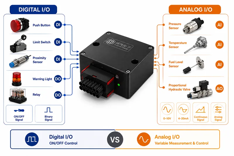
Digital and analog I/O modules are both used to connect field devices to a PLC, controller, or machine control system. The key difference is simple: digital I/O modules handle ON/OFF signals, while analog I/O modules handle continuously changing values.
In real machine design, however, the decision is not always just “digital or analog.” Engineers also need to consider signal range, output load, control accuracy, environmental conditions, and whether the device communicates through CAN Bus or traditional wiring.
This guide explains the practical differences between digital and analog I/O modules and shows how to choose the right signal type for industrial automation and mobile machinery applications.
What Is a Digital I/O Module?
A digital I/O module processes signals with only two states. These states may be described as ON/OFF, 1/0, true/false, open/closed, or active/inactive.
Digital I/O is commonly used when the controller only needs to know whether something has happened or when it only needs to turn a device on or off.
Digital Input: ON/OFF Signals from Switches and Sensors
A digital input receives a binary signal from a field device. Common digital input devices include:
- Push buttons
- Limit switches
- Proximity sensors
- Emergency stop switches
- Pressure switches
- Seat switches
For example, a limit switch may tell the controller whether a machine arm has reached a specific position. The signal is either active or inactive, so a digital input is suitable.
Digital Output: Commands for Relays, Lamps and Solenoid Valves
A digital output sends an ON/OFF command from the controller to a field device. Common digital output devices include:
- Relays
- Warning lights
- Buzzers
- Cooling fans
- Simple solenoid valves
For example, if a machine reaches an unsafe condition, the controller can turn on a warning light or buzzer through a digital output channel.
What Is an Analog I/O Module?
An analog I/O module processes continuously changing signals. Instead of only detecting whether a signal is ON or OFF, analog I/O can measure or control a range of values.
Analog I/O is used when the system needs to know “how much,” “how hot,” “how fast,” “how far,” or “how much pressure.”
Analog Input: Continuous Signals from Sensors
An analog input receives variable signals from sensors. Common analog input devices include:
- Pressure sensors
- Temperature sensors
- Fuel level sensors
- Position sensors
- Flow sensors
Common analog signal standards include:
- 0-5V
- 0-10V
- ±10V
- 4-20mA
For example, a hydraulic pressure sensor may output a 4-20mA signal. Different current values represent different pressure levels. The controller can use this signal to monitor system pressure in real time.
Analog Output: Variable Commands for Proportional Control
An analog output sends a variable control command to a device. It is commonly used when the system needs smooth or proportional control instead of simple ON/OFF control.
Common analog output applications include:
- Proportional hydraulic valves
- Variable speed drives
- Flow control devices
- Motor speed control systems
In mobile machinery, PWM outputs and H-Bridge outputs are also widely used for hydraulic valves, motor control, and motion control functions. This is one reason why a mobile machinery controller may need more advanced output functions than a standard digital I/O module.
Digital I/O vs Analog I/O: Key Differences
The simplest way to understand the difference is to look at the signal type. Digital I/O works with states. Analog I/O works with values.
| Feature | Digital I/O Module | Analog I/O Module |
|---|---|---|
| Signal type | ON/OFF, binary state | Continuously changing value |
| Typical input devices | Push button, limit switch, proximity sensor | Pressure sensor, temperature sensor, position sensor |
| Typical output devices | Relay, lamp, buzzer, simple solenoid valve | Proportional valve, speed controller, drive |
| Common signals | 24V ON/OFF, dry contact | 0-10V, 4-20mA, ±10V |
| Use case | Status detection and simple control | Measurement and variable control |
| Complexity | Lower | Higher |
0-10V, 4-20mA and Signal Conversion in Analog I/O
Analog signals represent real-world values through voltage or current. For example, a pressure sensor may convert hydraulic pressure into a 4-20mA signal, while a position sensor may output a 0-10V signal.
The controller or I/O module converts this electrical signal into a digital value that the software can process. This is usually called A/D conversion, or analog-to-digital conversion.
For analog outputs, the process works in the opposite direction. The controller calculates a control value and converts it into a voltage or current command. This is called D/A conversion, or digital-to-analog conversion.
Practical note: When selecting an analog I/O module, always confirm the required signal range. A 0-10V sensor cannot be connected to a module that only supports 4-20mA unless a signal converter is used.
How to Choose Between Digital and Analog I/O Modules
The best way to choose the right I/O module is to start from the field device, not from the module catalog.
Step 1: Identify the Field Device
First, list every sensor, switch, actuator, valve, lamp, relay, motor, and operator device connected to the machine.
Step 2: Ask What Signal the Device Uses
If the device only reports two states, it usually needs digital I/O. If the device sends or receives a changing value, it usually needs analog I/O.
Step 3: Confirm Voltage, Current and Load
After deciding whether the signal is digital or analog, confirm the electrical details:
- Input voltage
- Output voltage
- Signal range
- Current load
- Isolation requirements
- Protection requirements
Step 4: Consider Future Expansion
Machines often gain new functions after development begins. It is usually better to reserve extra I/O capacity than to redesign the system later.
Digital and Analog I/O in Mobile Machinery Controllers
In mobile machinery, I/O selection is often more complex than in basic industrial automation. Machines may include hydraulic systems, CAN Bus devices, operator displays, keypads, distributed I/O modules, and harsh outdoor working conditions.
Common examples include:
- Limit switch → Digital input
- Pressure sensor → Analog input
- Temperature sensor → Analog input
- Warning light → Digital output
- Simple solenoid valve → Digital output
- Proportional hydraulic valve → PWM output or analog output
For larger machines, using CAN Bus I/O modules can help reduce wiring complexity by placing I/O closer to sensors and actuators. This is especially useful when devices are spread across a boom, chassis, cab, rear body, or attachment area.
CAN Bus Devices Are Not Traditional Digital or Analog I/O
Not every device should be counted as a traditional digital or analog I/O channel. Some devices communicate through CAN Bus or another fieldbus network.
For example, a CAN Bus mobile machinery display can show sensor values, alarms, fault codes, and operating parameters without requiring many separate lamps and switches.
A programmable CAN Bus keypad can replace multiple traditional switches and send operator commands through CAN Bus instead of separate digital input wires.
This means I/O planning should include both physical I/O channels and network-connected devices.
Common Selection Mistakes
Mistake 1: Treating All Sensors as Digital Inputs
Some sensors are simple switches, but many sensors provide analog values. A pressure switch may be digital, while a pressure sensor is usually analog.
Mistake 2: Using Digital Output for Proportional Control
A simple digital output can turn a valve on or off. It cannot provide smooth proportional control unless the valve and controller are designed for PWM or analog command signals.
Mistake 3: Ignoring Signal Range
Analog devices must match the supported signal range of the I/O module. Always confirm whether the signal is 0-10V, 4-20mA, ±10V, or another standard.
Mistake 4: Choosing by Channel Count Only
A 32-channel I/O module may still be unsuitable if it does not provide the correct combination of digital inputs, digital outputs, analog inputs, and analog outputs.
Mistake 5: Ignoring the Working Environment
For mobile machinery, I/O modules may need protection against dust, water, vibration, voltage fluctuation, and temperature changes. Environmental requirements should be checked before final selection.
FAQ
What is the difference between digital and analog I/O modules?
Digital I/O modules handle ON/OFF signals, while analog I/O modules handle continuously changing signals such as pressure, temperature, level, flow, or proportional control commands.
Is a pressure sensor digital or analog?
A pressure sensor is usually analog because it measures a changing pressure value. A pressure switch, however, is usually digital because it only indicates whether pressure has reached a set point.
Is a solenoid valve digital or analog?
A simple solenoid valve is usually controlled by a digital output. A proportional hydraulic valve may require PWM output or analog output for variable control.
What does 4-20mA mean in analog I/O?
4-20mA is a common analog current signal. Different current values represent different measurement values, such as pressure, temperature, or flow.
Can one I/O module have both digital and analog channels?
Yes. Many controllers and I/O modules combine digital inputs, digital outputs, analog inputs, analog outputs, and communication interfaces in one device.
Final Thoughts
The difference between digital and analog I/O modules comes down to signal type. Digital I/O is used for ON/OFF signals. Analog I/O is used for continuously changing values and variable control.
For simple switches, relays, lamps, and basic solenoid valves, digital I/O is usually sufficient. For pressure sensors, temperature sensors, proportional valves, and speed control, analog I/O or PWM output may be required.
In mobile machinery, engineers should also consider CAN Bus communication, distributed I/O, environmental protection, wiring complexity, and future expansion.
The best selection method is to start with the field device: identify what signal it sends or receives, confirm the electrical requirements, and then choose the I/O module or controller that matches the machine’s actual needs.
Need Digital or Analog I/O for Mobile Machinery?
SonnePower provides rugged mobile machinery controllers, CAN Bus I/O modules, CAN Bus displays, and programmable CAN keypads for construction, agriculture, sanitation, mining, airport ground support, and special-purpose vehicles.
Contact Us