 Skip to content

Is CAN Bus AC or DC? Understanding CAN Electrical Signals
Table of Contents
Short Answer
A CAN bus is not AC.
It uses DC-referenced voltage levels and communicates through differential signaling between two wires: CAN_H and CAN_L.
Although CAN signals change rapidly over time, the bus itself is electrically DC-based, not an alternating-current system like AC power lines.
Why the AC vs DC Question Comes Up
This question usually arises when someone measures a CAN signal with an oscilloscope.
On the screen, CAN signals often appear as:
Fast-changing waveforms
Square-wave-like transitions
Signals that “move up and down” over time
To someone with a basic electrical background, this can resemble AC behavior at first glance.
However, a changing voltage does not automatically mean AC.
AC and DC describe how current flows, not whether a signal toggles between logic states.
What AC and DC Mean in Electrical Terms
Before classifying CAN, it helps to clarify the definitions.
DC (Direct Current)
Current flows in one direction
Voltage is referenced to a fixed ground
Most digital logic systems are DC-based
AC (Alternating Current)
Current reverses direction periodically
Voltage oscillates around zero
Commonly used for power transmission
CAN signaling does not involve current reversing direction in this way.
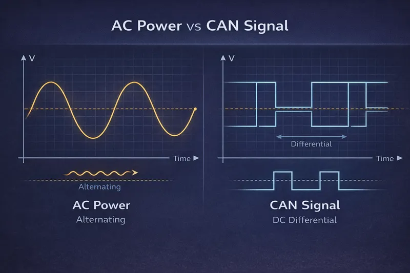
CAN Uses DC-Referenced Differential Voltages
CAN communication is based on DC voltage levels, not AC waveforms.
Key characteristics include:
Both CAN_H and CAN_L sit around a DC common-mode voltage
Data is encoded as the voltage difference between the two lines
Receivers evaluate the difference, not the absolute voltage
This is known as differential signaling, and it is fully compatible with DC-based digital electronics.
If you want a deeper explanation of why CAN relies on two physical signal lines, you can refer to our related article:
👉 Why Does a CAN Bus Need Two Wires?
CAN_H and CAN_L Voltage States
In a typical high-speed CAN system:
Recessive state
CAN_H and CAN_L are at nearly the same voltage
The differential voltage is close to zero
Dominant state
CAN_H rises slightly
CAN_L drops slightly
The receiver detects the voltage difference
At no point does the signal oscillate like AC power.
The system remains DC-referenced throughout operation.
Differential Signaling Is Not AC
This is one of the most common misconceptions.
Differential signaling ≠ AC signaling
Differential signaling means:
Two wires carry complementary DC-based signals
External noise affects both wires similarly
The receiver subtracts one signal from the other
This method improves noise immunity, but it does not change the fundamental DC nature of the signal.
Why CAN Does Not Use AC Signals
Using AC for a digital communication bus would introduce major drawbacks:
More complex decoding circuits
Unstable logic thresholds
Poor compatibility with microcontrollers and digital logic
DC-referenced signaling allows:
Simple transceiver design
Reliable interpretation of logic states
Easy integration into embedded control systems
This is why CAN, like most digital field buses, is DC-based rather than AC-based.
DC Does Not Mean “Stable” in Real Machines
While CAN signaling itself is DC-based, real-world DC power environments are rarely stable.
In off-highway and industrial machines, it is common to encounter:
Voltage spikes
Engine cranking drops
Load-dump events
Maintaining reliable CAN communication therefore depends not only on the protocol design, but also on how controllers handle DC power fluctuations at the hardware level.
This is a system-level concern, not just a signaling detail.
Common-Mode Voltage vs Differential Voltage
Another source of confusion is common-mode voltage.
In practice:
Both CAN_H and CAN_L float around a DC common-mode level
That level can shift due to ground differences
Communication still works because receivers care about the difference, not the absolute value
This tolerance is one of the reasons CAN performs well in large machines with imperfect grounding.
Signal Integrity and Field Diagnostics
When AC-like noise appears on a DC-based CAN signal, it usually points to:
Grounding issues
Shielding problems
Wiring or connector faults
—not to the presence of AC signaling.
Understanding this distinction is often the first and most critical step in diagnosing communication problems in the field.
Misinterpreting CAN signals as AC can lead to incorrect troubleshooting decisions and unnecessary system changes.
Signal Integrity and System Reliability
Because CAN uses DC-referenced differential signaling:
Electrical noise is largely rejected
Long cable runs remain stable
Multiple nodes can share the same bus reliably
These characteristics are essential in modern machine control architectures, where communication reliability is a baseline requirement of the entire system.
For a broader system-level perspective, you may also find this overview helpful:
👉 What Is a Mobile Machinery Control System?
Summary: Is CAN Bus AC or DC?
❌ CAN bus is not AC
✅ CAN bus uses DC-referenced voltage levels
✅ Data is encoded using differential signaling
✅ Rapid voltage changes do not imply AC current
CAN’s electrical design combines:
DC logic compatibility
Differential noise immunity
Robust operation in harsh environments
This combination is a key reason why CAN remains a standard communication technology in vehicles, mobile machinery, and industrial control systems.