Skip to content

What Is a CAN Bus Keypad and How It Works
Table of Contents
Modern machinery uses multiple ECUs, sensors, and safety logic, making hardwired switches unreliable and wiring-heavy. CAN Bus keypads solve these issues with fewer wires, higher durability, and software-defined control.
What Exactly Is a CAN Bus Keypad?
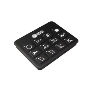
A CAN Bus Keypad is a distributed HMI node containing:
A matrix of momentary buttons
A microcontroller running a CAN protocol stack
RGB or single-color indicator LEDs
A sealed enclosure with high IP protection
A CAN transceiver (typically CAN 2.0B)
Deutsch/AMPSEAL/M12 interface connector
The keypad communicates over the CAN network using:
SAE J1939 (29-bit identifiers, PGN-based messaging)
CANopen (object dictionary, PDO/SDO communication)
Proprietary CAN frames (common for cost-optimized systems)
It functions as a standalone electronic control node, not just a passive switch.
Why Engineering Teams Choose CAN Bus Keypads
Wiring Harness Reduction at the System Level
A 12-key mechanical panel often requires:
12 signal wires
+24V supply
Ground
Illumination wiring
Relay or ECU input routing
A CAN keypad reduces all of this to:
CAN High
CAN Low
Power & Ground
This has system-level benefits:
Lower wiring mass → critical for mobile machines
Reduced failure points
Reduced assembly time & routing complexity
Simplified variant management (same keypad, different software mapping)
Improved Electrical Reliability & Noise Immunity
Traditional contact-based buttons suffer from:
Debounce issues
Voltage drops over long runs
EMI from solenoids, alternators, pumps
A CAN keypad leverages:
Differential signaling
Proper bus termination (120 Ω at both ends)
CRC validation at the frame level
Retry mechanisms and error confinement (per ISO 11898)
This results in far higher communication reliability, especially in harsh EMI environments.
True Software-Defined HMI Behavior
Rather than rewiring hardware, the keypad’s behavior is controlled by:
Button-to-function mapping tables
LED/indicator control commands
Press/hold/repeat profiles
Mode-dependent behavior (e.g., key disabled unless safety condition met)
This software-centric model enables:
Variant support
Optional equipment configuration
Reduced engineering time during machine updates
Over-the-air (OTA) configurable HMIs (on advanced systems)
Lifecycle & Environmental Robustness
Industrial-grade keypads offer:
Multi-million cycle key actuation
Fully gasketed enclosures
Potting or conformal coating for PCB protection
UV-stable polyester or silicone overlays
Wide temperature operating ranges (-40°C to +85°C)
These properties directly impact MTBF and warranty reduction.
CAN Bus Keypads at the Protocol Level
Using CANopen
Keypad is typically represented as:
RxPDOs for LED and backlight control
TxPDOs for button status
SDOs for configuration (node ID, debounce timing, brightness tables)
Typical object dictionary entries:
| Index | Description |
|---|---|
| 0x2000 | Button state bitfield |
| 0x3000 | LED mode configuration |
| 0x3001 | RGB color values |
| 0x1017 | Heartbeat time |
The keypad participates in NMT state transitions (Operational, Pre-op, Stopped).
Using SAE J1939
The keypad typically transmits:
Proprietary A/B PGNs for button events
29-bit extended identifier frames
SPN-encoded button states
It receives:
LED command PGNs
Brightness/illumination PGNs (diagnostic or proprietary)
Important engineering considerations:
Address claiming process (per J1939-81)
Ensuring PGN uniqueness across the vehicle
Priority fields for real-time HMI responsiveness
Custom CAN Implementations
Often used in cost-sensitive vehicles:
Button states encoded as bitfields in data bytes
Anti-ghosting and debounce handled in firmware
LED patterns controlled via simple CAN commands
Flexible but requires precise documentation for ECU integration
Electrical & Mechanical Architecture
Key Components
Microcontroller (ARM Cortex-M series is common)
CAN transceiver (e.g., MCP2551 or TJA1042)
RGB LED drivers (constant-current)
EMI filters and TVS protection
Overmolded or sealed enclosure
Environmental Performance
IP67/IP69K sealing
MIL-STD-202 or IEC 60068 vibration tests
UV exposure per ASTM G154
Chemical resistance (diesel, DEF, hydraulic oils)
Connector & Harness Design
Connector selection impacts:
Ingress protection
Field serviceability
Cross-platform compatibility
Deutsch DT/DTM series is most common for off-highway.
CAN Bus Keypads in System Integration
Topology Considerations
Keypad is typically placed:
At end-of-line nodes (terminator on keypad or external)
Near operator station
Away from high-interference zones (solenoids, alternators)
Bus Load Impact
Keypad traffic is low:
Button message rate: ~10–50 ms interval
LED command rate: on demand
This ensures minimal impact on total bus load, even in networks with high-frequency sensor PGNs.
Safety & Functional Behavior
For safety-critical machines:
Keypads can implement debounce windows
Press validation through dual reporting cycles
Interlocks handled at ECU level (preferred)
CANopen Safety or redundant networks can be used in advanced systems
Application Examples
Construction Machinery
Boom control modes
Auxiliary hydraulics
Lighting control
Attachment selection
Agricultural Equipment
PTO activation
Implement management
Section control (sprayers)
Specialty Vehicles
Fire pump engagement
Scene lighting
Outrigger controls
Snowplow raise/lower/angle functions
When to Choose a CAN Bus Keypad
Use cases where CAN keypads deliver significant engineering value:
Machines with >6 functions at the operator panel
Variants requiring flexible software configuration
Harsh environmental profiles
Weight or wiring constraints
J1939/CANopen-based vehicle architectures
Need for operator-state feedback (multi-color LEDs)
SonnePower CAN Bus Keypads
Conclusion
CAN Bus keypads have evolved from simple input devices into critical HMI nodes within modern distributed control systems. They drastically reduce wiring, improve environmental resilience, support software-driven customization, and integrate seamlessly with J1939 and CANopen networks.
For engineering teams designing the next generation of off-highway machinery, CAN keypads provide:
Lower system complexity
Higher reliability
Better user experience
Faster product variant development
Stronger modularity and future scalability
In short:
The CAN Bus Keypad is not just a modern convenience—it is the logical architectural choice for intelligent machinery.