Skip to content
Reducing Wiring Complexity with Distributed CAN I/O Modules
Table of Contents
Background
Wiring is often one of the most time-consuming and error-prone tasks in mobile machine development. In traditional centralized architectures, most sensors, actuators, and switches are routed back to a central control cabinet. This leads to numerous long wire runs, many crimped terminals, higher assembly labor costs, and dense harnesses that are difficult to service.
For system integrators, wiring complexity can significantly affect project schedules and profitability. Wiring errors frequently cause troubleshooting work, re-assembly, and unplanned machine downtime.
Distributed CAN I/O modules help address these challenges by locating input and output interfaces closer to the point of use. This shortens wiring runs, simplifies installation, and enables network-level diagnostics (for example, J1939-based fault reporting), resulting in more maintainable and reliable machine control systems.
Why Wiring Complexity Matters in Mobile Machinery
High Assembly Cost
Harness building and routing consume a significant share of electrical labor hours. A Rockwell Automation time study found that using an in-cabinet distributed I/O approach reduced wiring time by 66% compared with traditional point-to-point wiring.
Lower Wiring Errors
Harness building and routing consume a significant share of electrical labor hours. A Rockwell Automation time study found that using an in-cabinet distributed I/O approach reduced wiring time by 66% compared with traditional point-to-point wiring.
Difficult Serviceability
Dense harnesses make fault tracing and replacement time-consuming during field maintenance.
EMI Susceptibility
Long signal runs are more vulnerable to electromagnetic interference in high-power, noisy environments such as mining trucks and construction equipment.
How Distributed CAN I/O Modules Simplify Wiring
Node Placement Near Loads & Sensors
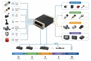
Distributed I/O modules are installed close to sensors and actuators, allowing short local pigtails for field devices. Only a single CAN and power cable is needed to connect the module to the network backbone.
Daisy-Chain CAN Topology
Modules connect in a linear CAN bus with termination resistors at both ends. This reduces cable bulk compared to star wiring, simplifies routing, and supports flexible node placement as the machine layout evolves.
Integrated Power and Signal
Modern modules often combine power distribution and I/O in one housing, reducing connector count and minimizing potential failure points.
Real-Time Diagnostics
Modules typically provide network diagnostics, transmitting input states, output currents, and fault data (e.g., via J1939 PGNs or CANopen PDOs). This makes it easier to locate wiring issues and enables remote troubleshooting through telematics.
System Architecture Example
Imagine a loader with 40 digital inputs, 24 digital outputs, and 8 analog sensors.
Centralized Approach
More than 64 signal wires would be routed to a single cabinet, and the total harness length could exceed 150 m.
Distributed Approach
Installing four CAN I/O modules near the lift arms, chassis, and rear frame can cut total harness length by approximately 40–60%, leaving only a single CAN backbone and power cable running front-to-rear.
This reduction means fewer clamps and splices and a lighter harness, which can help improve fuel efficiency and lower material costs.
Benefits for System Integrators
| Benefit | Impact |
|---|---|
| Faster Assembly | Pre-wired connectors and localized I/O can significantly reduce harness build hours and overall machine assembly time. |
| Lower Wiring Errors | Fewer terminations mean fewer opportunities for wiring mistakes and rework. |
| Reduced Troubleshooting Time | Built-in diagnostics help pinpoint failing inputs or outputs, reducing troubleshooting effort and downtime. |
| Scalable Design | Additional modules can be added to support new functions without redesigning the main harness. |
| Simplified Commissioning | Standard DBC files or CANopen EDS can speed up network integration with the master ECU. |
Key Design & Selection Checklist
When specifying distributed CAN I/O modules for harsh environments, system integrators should consider:
Node & Bandwidth Planning
Keep total bus utilization below about 70% to maintain acceptable latency and avoid arbitration delays.
Bus Length & Termination
Follow J1939 or CANopen guidelines (e.g., ≤40 m at 500 kbit/s) and install 120 Ω termination resistors at both ends of the trunk line.
Ingress Protection
Select modules rated IP67 or IP69K with sealed connectors to withstand water, dust, and high-pressure washdowns.
Voltage Range
Ensure wide supply compatibility (typically 8–32 V) and protection against reverse polarity, transients, and surges.
Diagnostics & LED Indication
Prefer modules with current monitoring, fault reporting, and clear LED status indicators.
Protocol Support
Choose modules supporting J1939, CANopen, or mixed-protocol networks, and ensure full documentation (DBC or EDS files) is provided for faster integration.
Extended Value Beyond Wiring
Weight Reduction
Shorter harnesses lower machine weight, improving fuel efficiency or extending battery runtime.
EMI Mitigation
Reduced signal path length minimizes susceptibility to noise and enhances system reliability.
Future-Proof Design
Modular I/O architecture supports easy addition of automation features or electrified subsystems in future upgrades.
Conclusion & Call to Action
Distributed CAN I/O modules are not just a wiring solution — they are a strategic enabler for faster assembly, easier maintenance, and scalable machine design. For system integrators facing tight deadlines and cost pressures, adopting a distributed architecture can dramatically improve efficiency and reliability.
Looking to cut wiring complexity in your next project?
Contact SonnePower to explore rugged CAN I/O modules, sample network layouts, and configuration files tailored for your machine platform.