 Skip to content

Isolated CAN Bus for Distributed IO Modules
Table of Contents
Electrical Stress on Distributed IO Modules
In mobile machinery such as excavators, agricultural equipment, cranes, and sanitation vehicles, distributed IO modules are typically installed close to actuators and sensors. These modules often interface directly with solenoid valves, relays, motors, and long sensor cables.
Compared with centrally mounted controllers, distributed IO modules operate in significantly harsher electrical environments, including high-current inductive loads, long wiring harnesses across large chassis structures, and unstable grounding conditions. As a result, the CAN interface of an IO module is exposed to substantial electrical stress.
In real-world applications, CAN communication failures in distributed systems are rarely caused by protocol issues. Instead, they are most often rooted in physical-layer electrical disturbances.
Failure Modes of Non-Isolated CAN
Ground Loops and Potential Differences
Large mobile platforms often exhibit noticeable ground potential differences due to welded frames, long cable runs, and multiple power distribution points. When a non-isolated CAN interface is used, these differences can form ground loops through CAN signal references or cable shields.
Typical symptoms include intermittent CAN errors, unexplained node resets, and communication instability during load operation. These failures are notoriously difficult to reproduce in laboratory conditions.
Inductive Switching Transients
Inductive loads such as solenoid valves, relays, and motors generate high-voltage transients when switching. Without isolation, these transients can couple directly into the CAN transceiver and MCU power domain, potentially causing communication errors or permanent damage.
Common-Mode Voltage Stress
Standard CAN transceivers typically tolerate a limited common-mode voltage range (for example, approximately −7 V to +12 V). In mobile machinery, events such as motor startup, welding repair, or large ground shifts can easily exceed this range.
When this happens, the CAN bus may experience error frames, bus-off conditions, or hardware failure.
EMI-Related Communication Errors
Distributed IO modules are often installed near motors, pumps, and hydraulic systems. Strong electromagnetic interference can increase CAN error rates, cause unstable communication, or lead to random node dropouts under specific operating conditions.
Isolated CAN Architecture
An isolated CAN bus introduces galvanic isolation between the CAN bus side and the internal logic domain of the IO module.
In mobile machinery applications, effective CAN isolation includes more than signal separation. A complete isolated CAN interface typically consists of digital isolation between the CAN controller and transceiver, an isolated CAN transceiver, and an isolated DC/DC power supply.
The isolated power supply is critical. Without power isolation, common-mode noise and transient disturbances can still couple into the system through the supply rails, reducing the effectiveness of signal isolation.
Why Isolation Matters for IO Modules
Direct Connection to Noisy Loads
Distributed IO modules interface directly with solenoid valves, high-current outputs, and long sensor cables. These connections are primary sources of electrical noise and transient energy.
Distributed System Topology
In distributed control architectures, IO modules may be powered from different sources, installed at varying distances, and referenced to different grounds. Isolation prevents electrical disturbances at one node from propagating through the CAN network.
Protection of Central Controllers
By isolating the CAN interface at the IO level, electrical faults are prevented from traveling upstream to the main controller or other CAN nodes, improving overall system robustness.
Engineering Benefits of Isolated CAN
From an engineering and lifecycle perspective, isolated CAN interfaces provide tangible benefits:
Elimination of ground loops between distributed nodes
Protection of MCU and logic circuits from voltage surges
Improved CAN stability during inductive load switching
Higher tolerance to wiring mistakes during installation and maintenance
Reduced after-sales cost by eliminating intermittent, hard-to-diagnose failures
These advantages directly translate into higher system uptime and improved field reliability.
Electrical Standards and Load Dump
Vehicle-based and mobile machinery systems must withstand electrical disturbances such as load dump, jump start, and inductive switching. These conditions are defined by standards such as ISO 7637-2 and ISO 16750.
Such events can generate voltage levels far beyond the tolerance of standard CAN transceivers. Isolated CAN interfaces help protect control electronics by electrically separating the communication bus from the internal logic domain, contributing to compliance with these demanding electrical requirements.
When Isolation Is Required
An isolated CAN interface should be considered essential for distributed IO modules under the following conditions:
24 V or 48 V electrical systems
Long CAN cable runs (typically greater than 3–5 meters)
High-power inductive loads connected to IO outputs
Outdoor or mobile equipment
Multi-node distributed control architectures
Environments with strong EMI or vibration
In these scenarios, isolation is not an optional feature but a necessary risk mitigation measure.
48V and Electrified Systems
As mobile machinery increasingly adopts electrification, 48 V systems and higher-voltage battery architectures are becoming more common. In these environments, CAN isolation is no longer merely recommended.
Isolation becomes a safety requirement to prevent high-voltage faults from propagating into low-voltage control networks and damaging sensitive electronics.
Practical Design Notes
Isolated CAN improves robustness, but it does not replace good engineering practice:
Proper EMC design, filtering, and cable routing remain essential
Correct CAN termination is still required
In distributed systems, cable shields are typically grounded at a single point (often at the main gateway) to avoid shield-induced ground loops
Isolation enhances reliability but does not compensate for poor system design.
Engineering Design Perspective
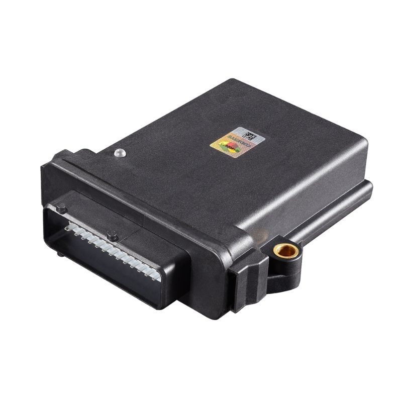
In real mobile and industrial control systems, some distributed IO modules integrate a built-in isolated CAN interface to ensure reliable operation under harsh electrical conditions.
This design choice reflects practical field experience rather than ideal laboratory assumptions. By addressing electrical stress at the physical and power-domain level, isolated CAN enables distributed IO modules to operate consistently throughout the equipment lifecycle.
Conclusion
Distributed IO modules operate at the intersection of control logic and harsh electrical environments. In such systems, CAN reliability depends not only on protocol implementation but on robust physical-layer and power-domain design.
An isolated CAN bus is a proven solution for protecting distributed IO modules from ground loops, voltage transients, EMI, and automotive-grade electrical disturbances, making it a key design consideration for modern mobile machinery and industrial control systems.