 Skip to content
How to Diagnose a Distributed I/O Module That Stops Responding in Mobile Machinery
Distributed I/O modules are increasingly used in mobile machinery to reduce wiring complexity and place inputs and outputs closer to sensors, valves, lights, and switches.
A typical architecture may look like:
Controller
     ↓
CAN Bus
     ↓
Distributed I/O Module
     ↓
Hydraulic Valves / Sensors / Lights / Switches
Under normal conditions:
- the controller sends commands,
- the I/O module receives data,
- outputs activate,
- sensors return feedback.
However, problems appear when:
The distributed I/O module suddenly stops responding.
Typical symptoms include:
- hydraulic valves no longer actuate,
- digital outputs stop switching,
- sensor data disappears,
- warning messages appear on displays,
- controller reports communication timeout.
Many engineers immediately suspect:
The I/O module has failed.
But in reality:
A non-responsive distributed I/O module is often caused by:
- power supply issues,
- CAN communication problems,
- incorrect node settings,
- wiring faults,
- output overload,
- or controller mapping errors.
This article explains a practical diagnosis process.
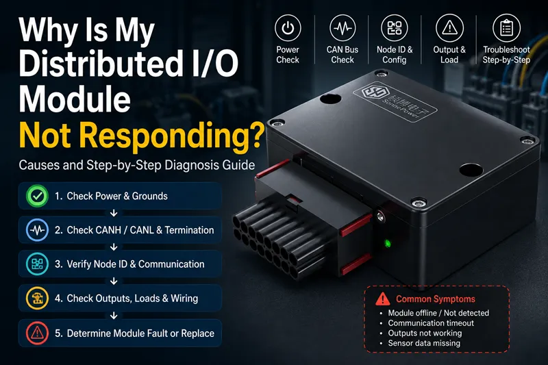
What “Distributed I/O Module Not Responding” Usually Means
“Not responding” does not always mean:
Module failure
Instead, it often means:
The controller cannot successfully communicate with the module.
This distinction matters.
Remote I/O Module Offline vs Channel Fault
Two different problems may occur:
Entire module offline
Symptoms:
- no communication
- timeout
- no LED activity
Possible causes:
- power loss
- CAN failure
- node conflict
Single channel failure
Symptoms:
Only one input/output stops working.
Possible causes:
- damaged sensor
- output overload
- wiring fault
The troubleshooting approach differs.
Controller Timeout vs Actual Module Failure
Some controllers trigger alarms simply because:
Expected response
↓
No response received within timeout period
This does not necessarily mean:
The module is broken
The cause may exist elsewhere.
Start with 24V Power Supply, Ground, and LED Status
Always begin with:
Power checks
before replacing hardware.
Check Module Power and Ground First
Measure:
- VIN
- GND
Confirm:
Expected supply voltage exists.
Examples:
- 12V systems
- 24V systems
No supply:
↓
No communication

Read Power, Communication, and I/O LEDs
Typical indicators:
| LED | Meaning |
|---|---|
| Power | Module powered |
| CAN | Communication active |
| I/O | Channel activity |
| Fault | Error present |
LED patterns often reveal issues quickly.
Inspect Connectors, Water Ingress, and Wiring Damage
Mobile machinery environments include:
- vibration
- dust
- moisture
- mud
- temperature cycling
Common failures:
- loose connectors
- corrosion
- water ingress
- damaged harnesses
Check CAN Bus Communication: CANH, CANL, and Termination
If power is normal:
Next:
Check communication.
Measure CANH and CANL Voltage
Typical idle values:
| Signal | Voltage |
|---|---|
| CANH | ~2.5V |
| CANL | ~2.5V |
Abnormal readings:
may indicate:
- short circuit
- wiring issue
- failed transceiver
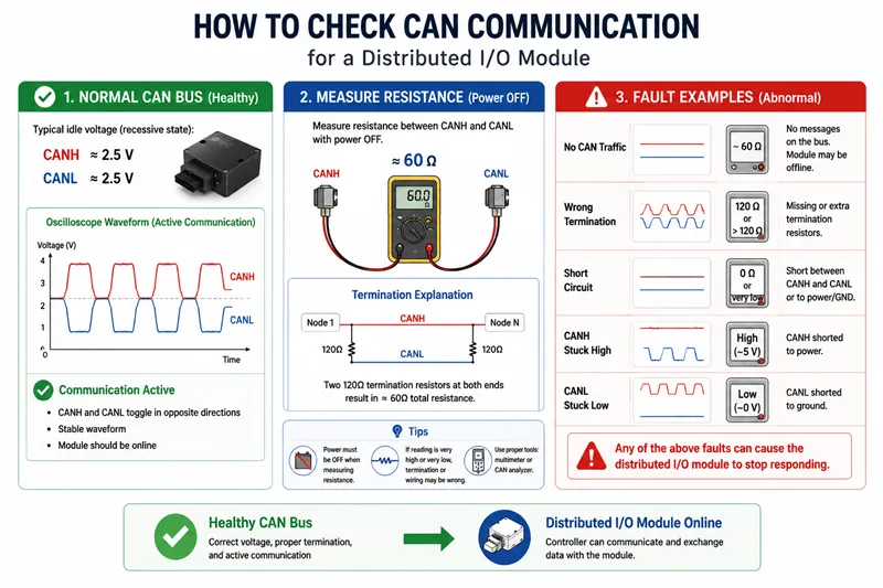
Check 120Ω Termination and Bus Resistance
Incorrect termination causes:
- unstable communication
- intermittent faults
- node dropout
Measure:
Resistance between:
CANH
and
CANL
Typical:
~60Ω total network resistance
Confirm CAN Traffic Before Replacing the Module
No traffic
↓
No communication
↓
Module appears offline
Use:
- CAN analyzer
- oscilloscope
- diagnostics software
Diagnose Node ID, Bit Rate, and Heartbeat Timeout
Incorrect configuration is common.
Node ID Conflict
Example:
Two nodes:
Node A = ID 5

Node B = ID 5
Conflict:
↓
Communication failure
Bit Rate Mismatch
Examples:
Controller:
250 kbps
I/O:
500 kbps
Result:
No communication
Heartbeat Timeout
Some systems monitor:
Heartbeat messages
No heartbeat:
↓
Node considered offline
Check Controller Logic and Mapping
The problem may not exist inside the I/O module.
Process Data Mapping Errors
Controller:
expects:
Output 3
I/O module:
receives:
Output 5
Result:
No action
Although communication exists.

Display Alarm vs Real I/O Status
Display warnings sometimes indicate:
Communication timeout
rather than:
Actual hardware damage
Look for Output Overload or Failed Loads
Outputs can fail because:
Connected devices fail.
Hydraulic Valve Coil Not Responding
Possible causes:
- damaged coil
- short circuit
- excessive current
Module protection may disable output.
Digital Output Overload
Excessive load:
↓
Protection triggered
↓
Output disabled
Sensor Input Missing
Missing signal:
does not always mean:
module fault
The sensor itself may be damaged.
When the Distributed I/O Module Is Actually Faulty
Only consider replacement after:
- power checks
- CAN checks
- configuration checks
- output checks
have been completed.
Water Damage or Corrosion
Signs:
- unstable communication
- overheating
- intermittent faults
Repair vs Replace
Replace when:
- repeated failures occur
- internal electronics damaged
- severe corrosion exists
Repair may be possible for:
- connectors
- harnesses
- external faults
Field Checklist for Distributed I/O Troubleshooting
Use this sequence:
Symptom

↓

Power Supply

↓

LED Status

↓

CANH / CANL

↓

Termination

↓

CAN Traffic

↓

Node ID

↓

Controller Mapping

↓

Output Load

↓

Module Replacement
Avoid:
Replacing modules before diagnosing communication and power conditions.
This wastes time and increases maintenance cost.