 Skip to content

CAN Bus Failures: How a Single ECU Destabilizes the Network
Table of Contents
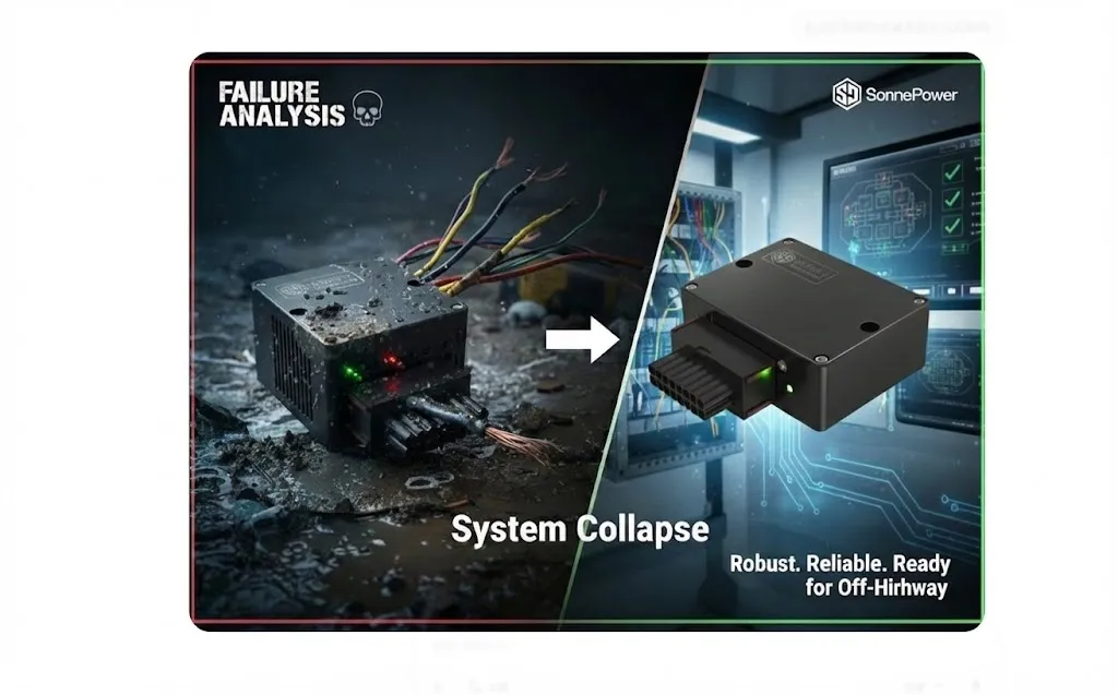
In mobile machinery control networks, a “total network collapse” is rarely caused by a physical cable break. Instead, it is often a cascading effect triggered by a single node’s abnormal behavior. Typical failure modes include a transceiver-level stuck dominant condition or a node in the Error Active state repeatedly triggering Active Error Flags, which consume the entire bus bandwidth. A robust system design relies on the error state machine defined in ISO 11898-1. When the Transmit Error Counter (TEC) exceeds 255, the node must enter the Bus-Off state and cease transmission, effectively isolating the fault to protect the rest of the network.
Physical Layer Conflict: From "Dominant Overwrite" to Idle State Disruption
The CAN bus utilizes “Wired-AND” logic, where the Dominant (0) level always overrides the Recessive (1) level.
The Mechanism
Normal communication requires the bus to return to a Recessive idle state between frames. If a faulty node or transceiver drives the bus Dominant continuously, the network cannot return to idle. This destroys the rules for Frame Start (SOF), Bit Stuffing, and End of Frame (EOF).
The Result
Other nodes cannot detect a valid inter-frame space to start transmission. Even if they attempt to send, they will immediately detect bit errors and enter error handling. Externally, the entire network appears “dead.”
Link Layer Storms: The Cascade Effect of Active Error Flags
When a node is in the Error Active state, its response to perceived errors is aggressive:
Active Error Flags
Upon detecting a CRC or Form error, the node sends an Active Error Flag consisting of six consecutive dominant bits. This intentionally violates bit-stuffing rules to ensure all other nodes synchronize on the error.
Bandwidth Exhaustion
Frequent error flags followed by automatic retransmissions can saturate the bus. In complex J1939 networks integrating HMIs, Joysticks, and high-density I/O, this “error storm” prevents critical control messages (such as steering or braking) from reaching their destination.
Startup Risks: Power Sequencing and Brown-out Conditions
In real-world off-highway applications, node instability often occurs during engine cranking.
Voltage Dips
The massive current draw during startup can cause 24V systems to dip below the critical operating threshold for MCUs or transceivers.
Undefined States
These transients (often governed by ISO 7637 standards) can leave a node in an undefined internal state. If the hardware power management is not resilient, a node may incorrectly drive the CAN transceiver before the CPU has fully initialized, causing a stuck dominant condition.
Fault Tolerance: From Detection to Bus-Off Isolation
To achieve a Fail-Silent system goal, controllers must strictly adhere to the ISO error state transitions:
State Degradation
A faulty node should transition from Error Active to Error Passive, where it can only send Recessive error flags, thereby losing the ability to disrupt the bus.
Bus-Off Isolation
Once the TEC exceeds 255, the node must enter Bus-Off and physically disconnect its logic from the bus.
Engineering Practice
In the design of industrial-grade controllers like the SonnePower SPC-SFMC series, ensuring the hardware determinism of TEC/REC counters is a core requirement. By providing observable diagnostic interfaces via CoDeSys 3.5, engineers can quickly identify the “rogue” node without hardware disassembly.
Engineering Best Practices for Robust Networks
Multi-Channel Partitioning
Use controllers with multiple CAN interfaces (such as the SPC-SFMC-X3632A, supporting up to 66 Total I/O) to partition the network. This allows you to isolate the powertrain from auxiliary attachments via gateway strategies.
Physical Integrity
Use IP67 sealed connectors and strictly enforce 120Ω termination matching to minimize intermittent error frames caused by signal reflections or moisture.
Resource Redundancy
Ensure the controller has sufficient CPU overhead to handle high-frequency error interrupts and diagnostic logging without compromising core control loops.
FAQ
Q: Why does the oscilloscope show "normal" CAN voltages, yet communication is completely down?
A: “Normal” voltages do not guarantee logical integrity. Common causes include: an Error Frame storm (nodes repeatedly sending error flags), failed ACK bits leading to continuous retransmissions, or mismatched baud rates/sample points. You should capture the bus traffic to check for a high frequency of “6-consecutive dominant bits” (Error Flags).
Q: How can I locate a faulty ECU without disconnecting devices one by one?
A: The most effective engineering method is to use a controller with multi-channel CAN isolation to segment the bus. Simultaneously, read the internal TEC/REC registers of the nodes. If using a SonnePower controller, you can monitor these counters in real-time to identify which node is approaching the Bus-Off threshold.