 Skip to content

CAN Bus 5V vs 3.3V: What Engineers Actually Need to Know
Table of Contents
Many engineers searching for “CAN Bus 5V vs 3.3V” are trying to answer a simple question:
Is CAN bus a 5V system or a 3.3V system?
The short answer is neither.
In reality, the “5V vs 3.3V” distinction usually refers to the CAN transceiver supply voltage or MCU logic interface, not the voltage level on the CAN bus itself.
Understanding this difference is important when designing CAN-based systems for embedded electronics, industrial controllers, or mobile machinery.
This guide explains the real differences between 3.3V and 5V CAN transceivers, how they interact with microcontrollers, and when each option makes sense.
Is CAN Bus Actually 5V or 3.3V?
A common misconception is that the CAN bus operates at either 5V or 3.3V logic levels.
However, CAN communication is based on differential signaling, not single-ended logic levels.
On a high-speed CAN network:
| Bus State | CAN_H | CAN_L | Differential |
|---|---|---|---|
| Recessive | ≈2.5V | ≈2.5V | 0V |
| Dominant | ≈3.5V | ≈1.5V | ≈2V |
The bus voltage is therefore determined by differential signaling behavior defined by ISO 11898, not the logic supply voltage of the transceiver.
This means the CAN bus itself does not operate at 3.3V or 5V logic levels.
Instead, the voltage difference appears in the device electronics connected to the bus.
Where the 5V vs 3.3V Difference Actually Comes From
The phrase “CAN Bus 5V vs 3.3V” usually refers to the CAN transceiver supply voltage or the logic interface with the microcontroller.
A typical CAN node contains three parts:
The CAN transceiver converts logic-level signals from the MCU into differential signals on the CAN bus.
Examples:
| Transceiver | Supply Voltage |
|---|---|
| MCP2551 | 5V |
| TJA1050 | 5V |
| SN65HVD230 | 3.3V |
| TCAN337 | 3.3V |
So the “5V vs 3.3V” question is really about the power rail used by the transceiver and the logic interface with the MCU.
Can 3.3V and 5V CAN Transceivers Work Together?
Yes.
In most cases 3.3V and 5V CAN transceivers can operate on the same CAN bus.
This is possible because the CAN differential signaling standard defines voltage thresholds, not the internal supply voltage of the device.
A compliant transceiver must generate a dominant differential voltage large enough for other nodes to detect, regardless of whether the device is powered from 3.3V or 5V.
As a result, mixed systems are common in real-world designs.
For example:
A 3.3V STM32 controller node
A 5V automotive ECU
A 5V industrial sensor
All can coexist on the same CAN network.
The Real Compatibility Risk: MCU Logic Levels
While the CAN bus itself is tolerant of mixed voltages, the logic interface between the MCU and the transceiver is where compatibility issues can occur.
Engineers should check:
TXD input voltage threshold
RXD output voltage level
VIO pin behavior (if present)
MCU input tolerance
Example scenario:
3.3V MCU
↓
5V CAN transceiver
↓
CAN bus
The key question becomes:
Can the MCU safely read the RXD output level from the transceiver?
Some transceivers output 5V logic on RXD, which may damage a 3.3V-only MCU input.
Many modern CAN transceivers solve this with a VIO pin, allowing the logic interface to operate at 3.3V while the transceiver core runs at 5V.
Do You Need a Level Shifter?
In many cases, no level shifter is required.
But it depends on the transceiver design.
A simple rule of thumb:
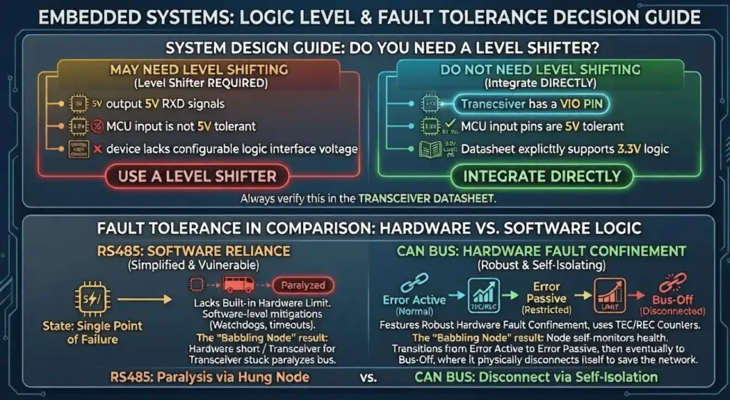
You usually do NOT need level shifting if:
the transceiver has a VIO pin
the MCU input pins are 5V tolerant
the datasheet explicitly supports 3.3V logic
You may need level shifting if:
the transceiver outputs 5V RXD signals
the MCU inputs are not 5V tolerant
the device lacks a configurable logic interface voltage
Always verify this in the transceiver datasheet.
When a 3.3V CAN Transceiver Makes More Sense
In modern embedded systems, 3.3V CAN transceivers are increasingly common.
Typical advantages include:
compatibility with modern 3.3V MCUs
reduced power consumption
simpler power supply design
fewer voltage rails required
This is particularly useful in:
IoT devices
robotics controllers
embedded industrial systems
When 5V CAN Transceivers Still Make Sense
Despite the growth of 3.3V electronics, 5V CAN solutions remain common in several industries.
Typical reasons include:
legacy automotive electronics
existing 5V system rails
compatibility with older CAN modules
industrial environments with established 5V designs
As long as the devices comply with the CAN physical layer requirements, mixed networks remain possible.
Common Design Mistakes with CAN Bus Voltage
Several common mistakes occur when engineers first design CAN networks.
Confusing bus voltage with logic voltage
CAN bus signaling is differential and not tied to the MCU supply voltage.
Ignoring RXD logic levels
Many compatibility issues occur on the logic interface, not on the CAN bus.
Assuming all CAN transceivers behave the same
Different transceivers provide different features such as:
VIO pins
standby modes
fault protection
Always check the datasheet.
Practical Decision Checklist for Engineers
Before choosing a CAN transceiver, verify:
MCU supply voltage
MCU input tolerance
transceiver supply voltage
RXD output voltage level
presence of a VIO pin
This simple checklist prevents most mixed-voltage design issues.
FAQ
Is CAN bus 5V or 3.3V?
Neither. CAN bus communication uses differential signaling between CANH and CANL, defined by the CAN physical layer standard. The 3.3V or 5V designation usually refers to the transceiver or MCU logic supply voltage.
Can 3.3V and 5V CAN transceivers work together?
Yes. In most cases they can coexist on the same CAN bus, as long as both devices meet the CAN physical layer requirements.
Do I need a level shifter between a 3.3V MCU and a 5V CAN transceiver?
Not always. Many modern transceivers provide a VIO pin or support logic-level compatibility with 3.3V systems.
What voltage does the CAN bus actually use?
Typical dominant state differential voltage is about 2V, created by approximately 3.5V on CANH and 1.5V on CANL.