 Skip to content
CAN Bus 5V vs 3.3V: What Mobile Machinery Engineers Should Actually Compare
Table of Contents
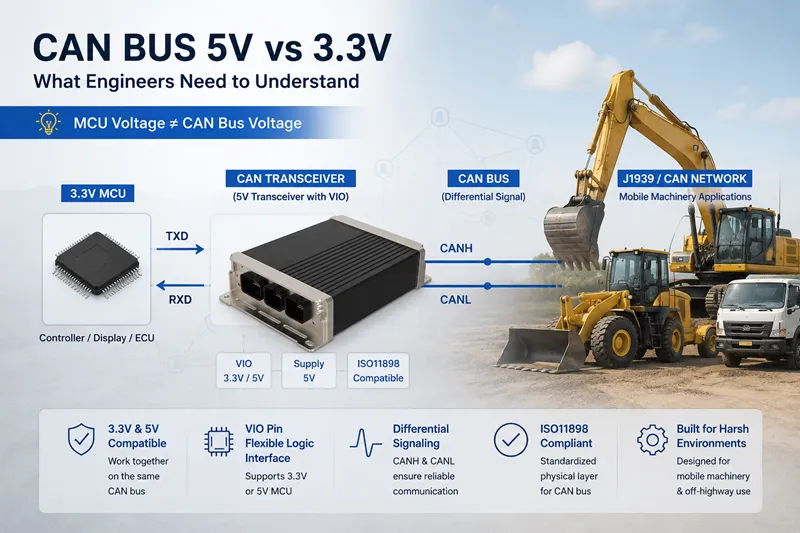
In modern CAN bus systems, engineers often encounter both 3.3V and 5V CAN devices.
Some controllers use 3.3V MCUs, while older CAN transceivers and industrial modules still operate at 5V.
This creates common questions:
- Can 3.3V and 5V CAN devices work together?
- Is CANH supposed to be 5V?
- Does a 3.3V MCU require a 3.3V CAN transceiver?
- Will mixed-voltage CAN networks become unstable in mobile machinery?
The short answer is:
3.3V and 5V CAN transceivers can usually communicate normally on the same CAN bus.
However, the real engineering details are often misunderstood.
This article explains the actual differences between 3.3V and 5V CAN systems, how CAN transceivers interact with MCU logic levels, and what engineers should check in mobile machinery and J1939 applications.
What Does 3.3V or 5V Mean in a CAN Bus System?
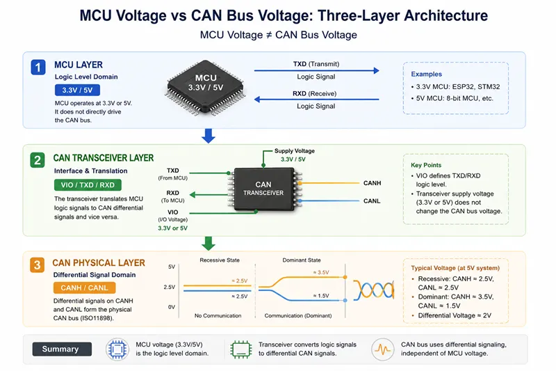
One of the biggest misunderstandings in CAN design is assuming that CAN bus voltage directly equals MCU voltage.
In reality, several different voltage domains exist inside a CAN system.
MCU Logic Voltage vs CAN Bus Physical Layer
The MCU may operate at:
- 3.3V
- 5V
But the CAN bus itself uses:
- CANH
- CANL
These are differential communication lines defined by ISO11898.
The MCU does not directly drive the CAN bus wires.
Instead:
MCU → CAN Transceiver → CANH/CANL
The CAN transceiver converts MCU logic signals into differential CAN signals.
CAN Transceiver Supply Voltage Explained
A CAN transceiver may operate from:
- 5V supply
- 3.3V supply
This supply voltage powers the transceiver itself.
It does not mean the CAN bus suddenly becomes a “3.3V CAN bus” or “5V CAN bus.”
Modern CAN transceivers are designed to meet standardized CAN physical layer requirements regardless of whether the chip itself uses 3.3V or 5V internally.
Why CANH and CANL Are Not Simple 5V Signals
CAN is not a normal GPIO communication interface.
It uses differential signaling.
Typical CAN voltage behavior:
| State | CANH | CANL |
|---|---|---|
| Recessive | ~2.5V | ~2.5V |
| Dominant | ~3.5V | ~1.5V |
The important value is the voltage difference between CANH and CANL.
Because of this:
Measuring CANH alone does not fully describe CAN communication quality.
Can 3.3V and 5V CAN Transceivers Work Together?
In most cases:
Yes.
As long as both transceivers comply with ISO11898 CAN physical layer standards, mixed-voltage CAN networks usually work normally.
ISO11898 Compatibility and Differential Signaling
CAN communication depends on:
- differential voltage
- bus timing
- common-mode range
- transceiver compliance
—not MCU supply voltage.
This is why:
- 3.3V CAN transceivers
- 5V CAN transceivers
can coexist on the same network.
This is extremely common in:
- J1939 systems
- mobile machinery
- automotive CAN networks
- mixed-generation equipment
Mixed 3.3V and 5V CAN Networks in Real Applications
A real machine may contain:
| Device | Internal Logic |
|---|---|
| Engine ECU | 5V |
| HMI display | 3.3V |
| I/O module | 5V |
| GPS module | 3.3V |
| Controller | 3.3V |
All devices can still communicate over the same CAN bus.
The key factor is:
CAN transceiver compatibility.
When Compatibility Problems May Still Happen
Problems usually come from:
- incorrect logic-level interfacing
- poor grounding
- low-quality CAN modules
- incorrect termination
- EMC interference
- long harness routing
—not because one device uses 3.3V internally.
3.3V MCU and 5V CAN Transceiver Design
Another common engineering question is:
Can a 3.3V MCU directly connect to a 5V CAN transceiver?
The answer depends on the transceiver design.
What the VIO Pin Does
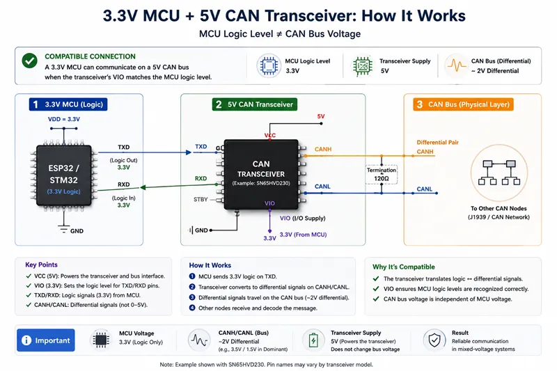
Many modern CAN transceivers include a VIO pin.
The VIO pin defines:
- TXD logic level
- RXD logic level
This allows the transceiver to communicate with:
- 3.3V MCU
- 5V MCU
while the CAN transceiver itself may still use 5V supply power.
This is one of the most important concepts modern CAN designers should understand.
TXD/RXD Logic Levels and MCU Compatibility
Without a VIO pin:
- RXD output voltage
- TXD input threshold
may not match the MCU safely.
This can cause:
- unreliable communication
- MCU pin overstress
- startup instability
Always check:
- TXD input threshold
- RXD output level
- MCU pin tolerance
before mixing voltages.
When Level Shifting Is Required
Level shifting may be necessary when:
- MCU pins are not 5V tolerant
- older CAN transceivers are used
- RXD outputs exceed MCU safe input voltage
Many older 5V CAN transceivers were designed before widespread 3.3V MCU adoption.
ESP32, STM32, and MCP2515 Common Design Examples
Many hobby and industrial developers use:
- ESP32
- STM32
- MCP2515
- SN65HVD230
- TJA1050
- TJA1051
Common confusion comes from mixing:
- 3.3V MCU boards
- 5V CAN modules
without checking logic compatibility.
Some cheap CAN modules may work temporarily but remain electrically unsafe long-term.
CANH and CANL Voltage Explained
Dominant State vs Recessive State
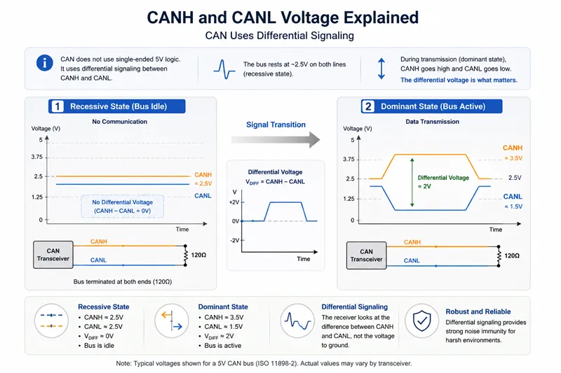
CAN bus uses two communication states:
Recessive State
Typical voltages:
- CANH ≈ 2.5V
- CANL ≈ 2.5V
Dominant State
Typical voltages:
- CANH ≈ 3.5V
- CANL ≈ 1.5V
Communication depends on the voltage difference.
Typical CAN Bus Voltage Measurements
During troubleshooting:
| Measurement | Typical Result |
|---|---|
| CANH to GND | 2.5V–3.5V |
| CANL to GND | 1.5V–2.5V |
| CANH–CANL differential | ~2V dominant |
These values vary slightly by transceiver design.
Why Measuring CANH Alone Can Be Misleading
A common mistake is:
“CANH is not 5V, so the CAN bus must be broken.”
This is incorrect.
CAN diagnosis should include:
- CANH/CANL differential voltage
- termination resistance
- oscilloscope waveform
- common ground condition
- communication status
—not just single-wire voltage checks.
3.3V vs 5V CAN in Mobile Machinery and J1939 Networks
Mobile machinery often combines devices from different suppliers and generations.
Mixed-voltage CAN networks are therefore extremely common.
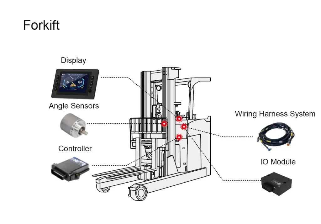
Controllers, Displays, and I/O Modules on the Same CAN Network
A modern machine may include:
- Controller
- CAN display
- keypad
- Distributed I/O module
- Hydraulic controller
- Telematics gateway
Some devices use 3.3V internal logic.
Others still use 5V architectures.
This normally does not prevent communication.
24V Vehicle Systems vs CAN Transceiver Voltage
Another common misunderstanding:
“The machine is 24V, so the CAN bus must be 24V.”
This is false.
The vehicle electrical system and CAN transceiver voltage are different design layers.
A machine may use:
- 24V battery system
- 5V CAN transceiver
- 3.3V MCU
simultaneously.
EMC, Ground Offset, and Long Harness Considerations
In mobile machinery, CAN reliability is often affected more by:
- EMC noise
- hydraulic pump interference
- grounding quality
- harness routing
- connector quality
than by whether the transceiver itself uses 3.3V or 5V internally.
Why J1939 Compatibility Depends on the Physical Layer
J1939 communication depends on:
- proper CAN physical layer
- bus timing
- termination
- shielding
- grounding
—not whether devices internally use 3.3V or 5V MCUs.
Common 3.3V vs 5V CAN Design Mistakes
Confusing MCU Voltage with CAN Bus Voltage
The most common misunderstanding is assuming:
3.3V MCU = 3.3V CAN bus.
This is incorrect.
Using Non-5V-Tolerant MCU Pins
Some engineers directly connect:
- 5V RXD outputs
- to 3.3V-only MCU pins
without checking tolerances.
This may damage the MCU over time.
Ignoring Termination and Ground Reference
Many CAN problems blamed on “voltage mismatch” are actually caused by:
- missing 120Ω termination
- bad grounding
- excessive stub length
- connector corrosion
Assuming All CAN Modules Are Logic-Compatible
Low-cost CAN modules vary significantly.
Some are designed only for 5V systems.
Others include proper VIO support.
Always verify the datasheet.
How to Choose Between 3.3V and 5V CAN Transceivers
Power Consumption and PCB Design
3.3V transceivers often help reduce:
- power consumption
- PCB complexity
especially in modern embedded systems.
Industrial vs Mobile Machinery Applications
Mobile machinery environments require:
- strong EMC protection
- wide temperature tolerance
- transient protection
- vibration resistance
These factors are usually more important than transceiver supply voltage alone.
Industrial vs Mobile Machinery Applications
When upgrading or retrofitting machinery:
always check:
- logic-level compatibility
- VIO support
- ISO11898 compliance
- protection features
- EMC performance
before mixing CAN devices.
FAQ
1.Can 3.3V and 5V CAN transceivers work together?
Yes. ISO11898-compatible CAN transceivers can normally communicate on the same CAN bus network.
2.Is CANH always 5V in a 5V CAN system?
No. CANH and CANL are differential communication lines, not simple fixed-voltage GPIO signals.
3.Does a 3.3V MCU need a 3.3V CAN transceiver?
Not always. Many 5V CAN transceivers support 3.3V MCU logic through VIO pins or compatible TXD/RXD levels.
4.Is a 3.3V CAN transceiver less reliable than a 5V version?
Not necessarily. Reliability depends more on EMC design, protection, grounding, and transceiver quality than supply voltage alone.
5.What is the purpose of the VIO pin?
The VIO pin allows CAN transceivers to interface with different MCU logic voltages such as 3.3V or 5V.
6.Can ESP32 communicate with a 5V CAN network?
Yes, if the CAN transceiver supports compatible logic-level interfacing with the ESP32.