 Skip to content
Why HMI Cannot Read ECU Data on J1939 Networks
Table of Contents
In many mobile machinery projects, the HMI display powers on normally, but engine RPM, coolant temperature, fuel level, or diagnostic information does not appear on the screen.
The display may show:
- RPM = 0
- ECU Not Detected
- No Data Available
- CAN Communication Error
This problem is common in:
- construction equipment
- agricultural machinery
- sanitation vehicles
- mining machines
- retrofit control systems
In many cases, the issue is not caused by a damaged display. The root cause is usually related to J1939 communication, CAN bus configuration, PGN mapping, or physical layer problems.
This article explains the most common reasons why an HMI cannot read ECU data on a J1939 network and how engineers can diagnose the problem step by step.
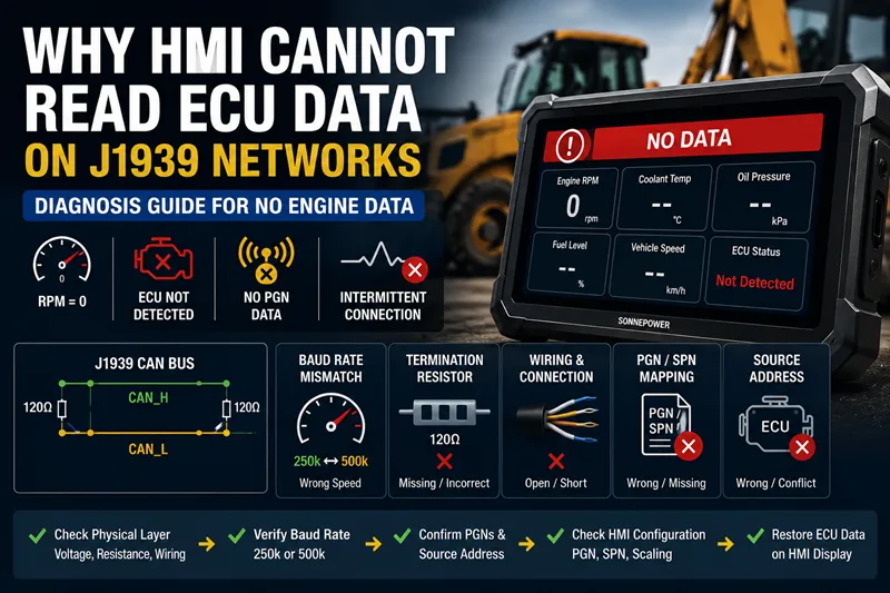
Common Symptoms of No ECU Data
Engine RPM Stays at Zero
One of the most common symptoms is that engine RPM always remains at zero even though the engine is running normally.
This usually means the HMI is not receiving or decoding the engine speed PGN correctly.
Possible causes include:
- wrong baud rate
- missing PGN
- ECU offline
- wrong source address
- CAN wiring fault
ECU Not Detected
Some displays or CAN diagnostic tools may show:
- ECU Not Found
- No J1939 Device
- No Communication
This can happen when:
- the ECU is powered off
- the CAN network is damaged
- the HMI is configured for the wrong CAN speed
- the display is connected to the wrong CAN channel
Engine Data Appears Intermittently
In retrofit projects, data may appear briefly and then disappear.
Typical symptoms include:
- RPM freezes
- coolant temperature disappears
- fuel data updates slowly
- random communication loss
This often indicates:
- unstable CAN wiring
- grounding problems
- poor connector contact
- intermittent baud mismatch
Check the J1939 Physical Layer First
Before changing HMI settings, engineers should first verify the physical CAN bus layer.
Measure CAN_H and CAN_L Voltage
A healthy J1939 network usually shows:
- CAN_H ≈ 2.5V to 3.5V
- CAN_L ≈ 2.5V to 1.5V
Abnormal voltage may indicate:
- short circuits
- damaged transceivers
- grounding issues
- wiring faults
Use a multimeter or CAN analyzer to measure voltage directly at the diagnostic connector or ECU connector.
Check Termination Resistors
J1939 networks normally use two 120Ω termination resistors.
When measured between CAN_H and CAN_L with power OFF, the network should measure approximately:
Req=120×120120+120=60 ΩR_{eq}=\frac{120\times120}{120+120}=60\ \OmegaReq=120+120120×120=60 Ω
If resistance is incorrect:
- missing resistor
- extra resistor
- damaged wiring
may prevent stable communication.
Inspect Wiring and Grounding
Many mobile machinery communication problems are caused by:
- loose connectors
- corrosion
- vibration damage
- grounding problems
- hydraulic EMI interference
Long wiring harnesses in off-highway vehicles can make communication especially sensitive to grounding quality.
Verify the Baud Rate: 250k vs 500k
Why Wrong Baud Rate Causes No Data
J1939 communication depends on precise CAN timing.
If:
- the ECU transmits at 250k
- the HMI listens at 500k
the display cannot correctly interpret the CAN frames.
The result is usually:
- no engine data
- ECU not detected
- communication timeout
- missing PGNs
Mixed 250k and 500k Networks
This commonly happens in retrofit projects where:
- a new HMI is added
- an aftermarket controller is installed
- a telematics gateway is integrated
Many older engine ECUs still use 250k, while newer devices may default to 500k.
Scan Both Baud Rates
Most CAN analyzers support:
- 250k
- 500k
- auto detection
If no messages appear at 500k, engineers should immediately test 250k.
This is often the fastest way to identify baud mismatch problems.
Confirm the ECU Is Sending Correct PGN Data
Even if CAN traffic exists, the HMI may still show no data if the required PGNs are missing.
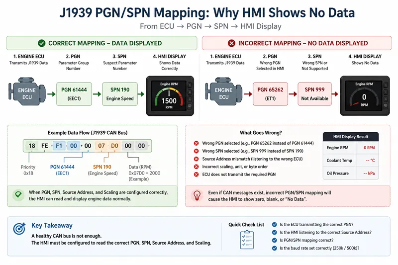
Engine RPM PGN
Engine RPM is commonly transmitted through:
- PGN 61444
- SPN 190
If the ECU does not transmit this PGN, RPM will remain zero on the display.
Missing or Invalid Data
Sometimes the ECU transmits:
- Not Available
- Error Indicator
- invalid values
instead of actual engine data.
This may happen when:
- the engine is not fully initialized
- another controller blocks communication
- PGN requests are missing
Zero Value vs No Data
Engine RPM = 0 does not always mean communication failure.
There is a difference between:
- valid zero value
- missing PGN
- invalid SPN
- unavailable data
Engineers should verify raw CAN data before replacing hardware.
Common HMI Configuration Problems
Wrong PGN/SPN Mapping
Many HMI displays require manual mapping of:
- PGNs
- SPNs
- source addresses
If mapping is incorrect, the display may receive CAN traffic but still show blank values.
Wrong CAN Channel Selected
Some displays support multiple CAN ports.
If the HMI listens on the wrong CAN channel, no ECU data will appear.
This is especially common in:
- dual-CAN systems
- telematics installations
- multi-network machinery
Incorrect Scaling or Byte Order
Incorrect:
- scaling
- endian configuration
- byte order
may cause:
- unrealistic values
- unstable data
- unreadable parameters
even though communication exists.
Step-by-Step Diagnostic Workflow
Step 1 — Check Power and Ground
Verify:
- ECU power
- HMI power
- CAN ground integrity
before testing communication.
Step 2 — Measure CAN Resistance
With power OFF:
- measure between CAN_H and CAN_L
- expected value ≈ 60Ω
Incorrect resistance usually indicates termination problems.
Step 3 — Scan J1939 Traffic
Use a CAN analyzer to:
- scan at 250k
- scan at 500k
- confirm active PGNs
This helps identify baud mismatch quickly.
Step 4 — Verify PGNs and Source Address
Check:
- required PGNs exist
- source address matches HMI configuration
- engine ECU is transmitting expected data
Step 5 — Verify HMI Settings
Confirm:
- baud rate
- CAN channel
- PGN mapping
- scaling
- SPN configuration
before replacing the display.