 Skip to content

How Many Modules or Nodes Can Be Connected to a J1939 CAN Bus?
Table of Contents
Short Answer
A commonly cited J1939 physical-layer answer is 30 nodes, or 30 ECUs, on one J1939 CAN bus. That figure appears in summaries of the J1939/11 physical layer alongside other baseline parameters such as 250 kbit/s and 40 m bus length.
But that is not the whole story. J1939 also uses an 8-bit ECU address space, which means there are up to 256 possible address values in theory. The reason engineers still hear “30 nodes” is that logical address space and practical network capacity are not the same thing. One is about how devices are identified; the other is about how many devices the physical network can support reliably.
So if you are asking how many modules or nodes can be connected to a J1939 bus, the practical answer is usually:
About 30 nodes by the common J1939/11 physical-layer guideline, even though the protocol address model supports far more theoretical addresses.
Why Two Different Numbers Exist: 30 Nodes vs 256 Addresses
This is the part many articles mention but do not fully explain.
J1939 network management uses 8-bit ECU addresses, which creates a theoretical pool of 256 address values. That sounds like the network should be able to host 256 devices, but that is not how real machine networks work. Copperhill’s J1939 address-claim discussion makes this distinction clear: the address field allows a large logical space, but SAE limits the practical network to a much smaller number of nodes.
In other words:
256 addresses = theoretical logical addressing space
30 nodes = commonly cited practical/physical-layer network limit for J1939/11
That difference matters because many engineers and buyers accidentally mix up address capacity with stable network capacity. They are not the same thing.
What Counts as a Node on a J1939 Network?
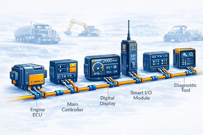
In real projects, a “node” usually means any electronic device with its own J1939 interface and network address. That typically includes ECUs, but it can also include displays, controllers, gateways, and smart accessory modules if they actively participate on the bus. Copperhill’s explanation of J1939 addressing supports this practical view: devices that claim addresses and communicate on the network are part of the node count.
So in a heavy equipment network, the following usually count as nodes if they are J1939 devices:
engine ECU
transmission ECU
vehicle controller
digital display / HMI
telematics gateway
smart I/O module
diagnostic interface module
accessory controller
This is why node count can climb faster than some teams expect. They may initially count only “main ECUs,” then later realize the display, logger, or gateway also occupies its own network address.
Why the 30-Node Rule Exists
The 30-node figure is not just an arbitrary protocol number. It is tied to the physical layer, which is why Kvaser lists it together with 250 kbit/s and 40 m for J1939/11.
That tells you something important: node count is part of a bigger system design constraint. It is connected to:
bus loading
transceiver electrical characteristics
wiring length
signal integrity
overall traffic on the network
So when engineers ask, “Can I just add one more module?” the answer is not only about whether another address exists. It is also about whether the physical network can still behave predictably once that device is added.
What Happens If You Push the Network Too Far?
Many pages stop at “30 nodes maximum,” but that does not help much in actual machine design. The real question is what happens when you move toward or beyond that number.
As node count increases, the network usually becomes more sensitive to design quality. More devices can mean more electrical loading, more traffic, more opportunities for address conflict, and less margin for poor wiring or topology decisions. J1939 does not instantly stop working the moment a project reaches the 31st device, but the network can become harder to keep robust if other constraints are also unfavorable. The standards summaries and address-claim discussions imply this practical distinction between theoretical possibility and recommended operation.
In project terms, that can lead to:
slower troubleshooting
less expansion margin
more sensitivity to cable routing and termination
greater chance of unstable communication when multiple systems are active
So the engineering question should not be:
“Can I physically connect one more device?”
It should be:
“Can I still guarantee stable communication after I add one more addressed device?”
Why Heavy Equipment Networks Reach the Limit Faster Than Expected
In heavy equipment, the node count problem is rarely just theoretical. A machine may start with only a few essential controllers, but modern architectures often add many more devices over time.
A typical machine might include:
engine ECU
transmission controller
main vehicle controller
digital display
GPS/telematics unit
diagnostic bridge
hydraulic subsystem controller
smart attachment module
As machines become more connected and feature-rich, the J1939 network can fill up faster than the original architecture team expected. This is especially true when optional features, retrofit modules, or third-party equipment are added later.
That is one reason the topic matters so much for off-highway and heavy-duty systems. The 30-node rule is not just a spec-sheet detail. It is a planning constraint.
What Engineers Often Misunderstand
The most common misunderstanding is this:
If J1939 has 256 addresses, why can’t I use 256 devices?
Because the address field is a logical protocol feature, while the 30-node figure is tied to the physical network environment defined for J1939/11. Copperhill explicitly explains that the address field is broader than the practical network node limit. Kvaser’s standards overview reinforces that the physical-layer specification is where the 30-node number comes from.
Another misunderstanding is assuming only “major ECUs” count. In practice, any module that joins the bus as its own addressed J1939 participant is usually part of the node count. That includes some displays, gateways, and smart peripherals.
A third misunderstanding is treating node count as the only design variable. It is not. Even a network under 30 devices can perform badly if length, wiring, topology, traffic, or termination are poorly managed.
What Counts More Than Raw Device Quantity
A bus with fewer than 30 devices is not automatically healthy. A bus close to 30 devices is not automatically broken. What matters is the complete network context.
The most relevant design factors include:
actual number of addressed devices
bus length
bit rate
message traffic density
physical topology
transceiver behavior and electrical load
termination quality
This is why good network planning is more valuable than memorizing one number. The 30-node rule is useful, but only when interpreted as part of a broader design envelope.
How to Plan Node Count in a Real Project
A practical J1939 network planning approach usually looks like this:
1. Count every addressed device
Do not count only major controllers. Include displays, gateways, smart I/O, and any accessory module that appears as its own J1939 participant.
2. Check physical-layer assumptions
If you are using a network built around the common J1939/11 assumptions, remember the standard summary ties 30 nodes, 250 kbit/s, and 40 m together.
3. Leave expansion margin
Do not design a production machine network so tightly that every future option requires a redesign. Leave space for service tools, attachments, optional modules, or later feature growth.
4. Separate protocol theory from field reality
A device may be able to claim an address in theory, but that does not guarantee a robust field network under real operating conditions.
5. Reassess when retrofits are added
A machine that was stable when shipped may behave differently after extra gateways, retrofit displays, or telematics units are added.
What This Means for Displays, Controllers, and Gateways
This topic is especially important for machine electronics suppliers. A display, controller, or gateway is not just a passive viewer of the network. In many cases it is an active J1939 participant, which means it may consume one of the available node slots on the bus.
That matters in real integration work. When OEMs add a rugged display, a telematics device, or a smart controller, they are not just adding features. They may also be consuming node capacity and increasing system traffic. That is why node planning should be part of HMI, controller, and gateway selection from the beginning.
For example, if a machine already includes engine, transmission, hydraulic, attachment, and telematics modules, then adding a new display or smart controller may affect more than just the wiring diagram. It may affect the practical margin of the whole J1939 network.
Final Answer
So, how many modules or nodes can be connected to a J1939 CAN bus?
The commonly cited answer is 30 nodes on a J1939/11 physical-layer network. At the same time, J1939 uses an 8-bit ECU address field, which creates 256 theoretical address values. These two numbers are not contradictory: one describes logical addressing space, and the other reflects the practical physical-layer limit most often associated with the standard.
The most useful takeaway is this:
Do not treat 256 addresses as 256 safe devices.
In real machine networks, you need to count all addressed modules and evaluate node count together with bus length, bitrate, and physical-layer design.