 Skip to content

Common CAN Bus Problems & Troubleshooting Guide for Engineers
Table of Contents
The Controller Area Network (CAN bus) is widely used in automotive systems, mobile machinery, agricultural equipment, and industrial automation due to its robustness and fault-tolerant design.
However, when a CAN network fails, it usually fails at the worst possible moment—during commissioning, field operation, or on-site maintenance.
If you are reading this article, chances are:
You have a multimeter in your hand
The system is not communicating
And you need answers now
This guide focuses on the most common CAN bus problems, how they present in real systems, what typically causes them, and how engineers troubleshoot them in the field.
Short Answer: What Are the Most Common CAN Bus Problems?
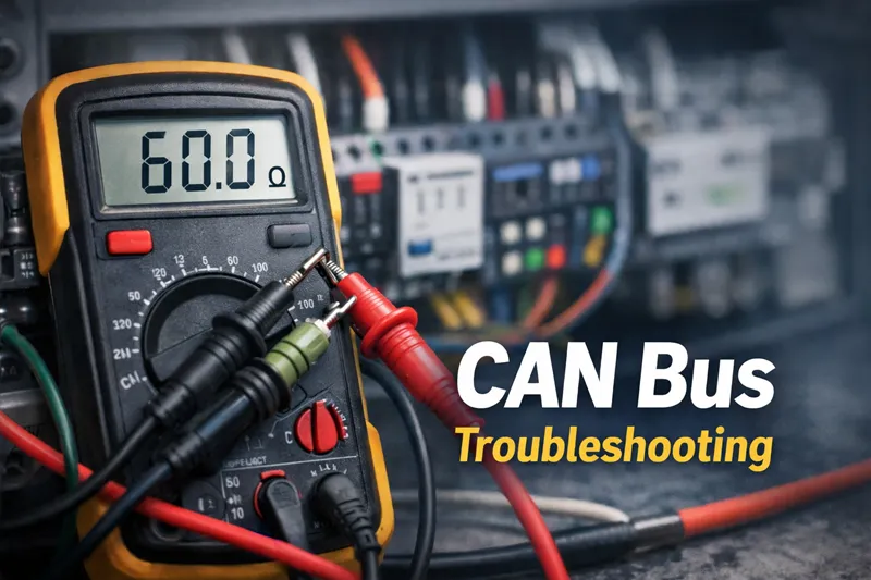
The most common CAN bus problems are caused by physical-layer issues and configuration errors, including incorrect termination resistance, wiring faults, EMI noise, baud rate mismatches, and faulty CAN transceivers. These issues often lead to symptoms such as no communication, intermittent data loss, error frames, or bus-off states.
👉 If you are diagnosing a “dead” CAN network, always start with termination resistance and voltage checks before replacing hardware.
Common CAN Bus Symptoms
CAN bus issues usually appear first as system-level symptoms, not obvious hardware failures. Correctly identifying the symptom greatly shortens troubleshooting time.
Network-Level Symptoms
No Communication (“Dead Network”)
No CAN messages visible on diagnostic tools
All nodes appear offline or unresponsive
Commonly caused by:
Broken wiring
Missing termination
Shorted CAN lines
Intermittent Communication
Messages appear and disappear
System works only under certain conditions (temperature, vibration, engine running)
Often linked to:
Loose connectors
Marginal termination
EMI or grounding issues
Intermittent faults are especially common in mobile machinery, where vibration and electrical noise are unavoidable.
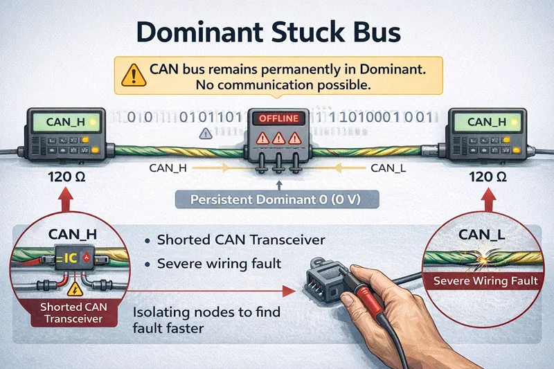
Dominant Stuck Bus
CAN bus remains permanently in a dominant state
No successful communication possible
Typically caused by:
Shorted CAN transceiver
Severe wiring fault
When this occurs, isolating nodes one by one is usually faster than inspecting the entire harness at once.
Error-State Symptoms
Frequent Error Frames and Retransmissions
Heavy bus traffic with repeated retries
Reduced effective bandwidth
Indicates signal integrity or timing issues
Bus-Off State
A node disconnects itself from the bus
Triggered when error counters exceed protocol limits
Usually caused by persistent physical-layer or configuration problems
Bus-off is not a random failure—it is a protective mechanism built into the CAN protocol.
Error Active / Error Passive Transitions
Node changes communication behavior due to accumulated errors
Suggests chronic instability rather than a one-time fault
These transitions are strong indicators that the root cause has not yet been resolved.
Common Root Causes of CAN Bus Problems
Most CAN bus issues can be traced back to two categories:
Physical-layer problems
Configuration or node-related faults
Physical Layer and Wiring Issues
Incorrect Termination Resistance
CAN requires two 120 Ω termination resistors, one at each end of the bus.
Quick Resistance Reference (Power Off):
| Measured Resistance (CAN_H ↔ CAN_L) | Meaning |
|---|---|
| ~60 Ω | ✅ Correct termination |
| ~120 Ω | ⚠️ One terminator missing |
| < 40 Ω | ⚠️ Extra termination |
| ~0 Ω | ❌ Short circuit |
Incorrect termination is one of the most common and easiest CAN bus problems to diagnose.
EMI, Noise, and Grounding Problems
In practice, many CAN bus problems attributed to “mysterious behavior” are actually caused by electromagnetic interference.
Standard industrial components often operate with minimal EMC margin, making CAN communication unstable in:
Mobile machinery
Construction equipment
Electrified or high-current environments
This is why CAN networks used in harsh environments typically rely on rugged, high-EMC-rated I/O modules and controllers, rather than general-purpose components.
Configuration and Node Faults
Baud Rate or Bit Timing Mismatch
Nodes configured at different bit rates cannot communicate
Symptoms often resemble wiring faults
Always verify:
Bit rate
Sample point
Synchronization settings
A mismatch here can make a healthy physical layer appear completely dead.
Device Configuration Issues
Incorrect node IDs
Message filtering blocking valid frames
Misconfigured gateways or bridges
Faulty ECU or CAN Transceiver
Field experience shows that:
Welding operations
Overvoltage events
Improper grounding during maintenance
are silent killers of CAN transceivers.
Controllers designed for harsh environments typically include redundant protection circuits to survive these real-world conditions—an important factor when long-term system uptime matters more than initial hardware cost.
Practical CAN Bus Troubleshooting Workflow
A structured troubleshooting approach saves time and prevents unnecessary component replacement.
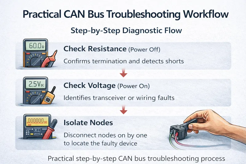
Step-by-Step Diagnostic Flow
Step 1: Check Resistance (Power Off)
→ Confirms termination and detects shorts
Step 2: Check Voltage (Power On)
→ Identifies transceiver or wiring faults
Step 3: Isolate Nodes
→ Disconnect nodes one by one to locate the faulty device
This workflow aligns with most professional CAN diagnostic procedures and resolves the majority of field issues.
Using Error States to Find Root Causes
CAN’s built-in error handling is a powerful diagnostic tool:
Frequent error frames → EMI, reflections, or timing issues
Error passive state → persistent but recoverable faults
Bus-off state → severe, repeated failures requiring corrective action
Summary: Common CAN Bus Problems at a Glance
The most frequent CAN bus problems include:
No or intermittent communication
Dominant stuck bus conditions
Frequent error frames and bus-off events
Incorrect termination and wiring faults
Baud rate mismatches and configuration errors
Damaged ECUs or CAN transceivers
While CAN is a highly robust protocol, most failures originate at the physical layer, often amplified by harsh environments and marginal hardware design.
In practice, prevention is more effective than repeated troubleshooting. Systems built with proper EMC protection, robust transceivers, and field-ready design principles experience far fewer CAN-related issues over their lifetime.
FAQ
What does 120 Ω resistance mean on a CAN bus?
It usually indicates that one termination resistor is missing.
What causes a CAN bus-off state?
Persistent communication errors caused by wiring faults, EMI, or faulty nodes.
How do you troubleshoot CAN bus communication problems?
Start with resistance and voltage checks, then isolate nodes and analyze error states.